Faraday report to Trinity House 16 September 1840
Report of Professor M. Faraday on his examination of the Apparatus for the Gibraltar Light House, dated 16th Septr. 1840
To the Master, Deputy Master1, and Elder Brethren of the Trinity House.
My Lords and Gentlemen,
87. I have continued the examination of the Gibraltar Lighthouse apparatus and beg leave to state the results.
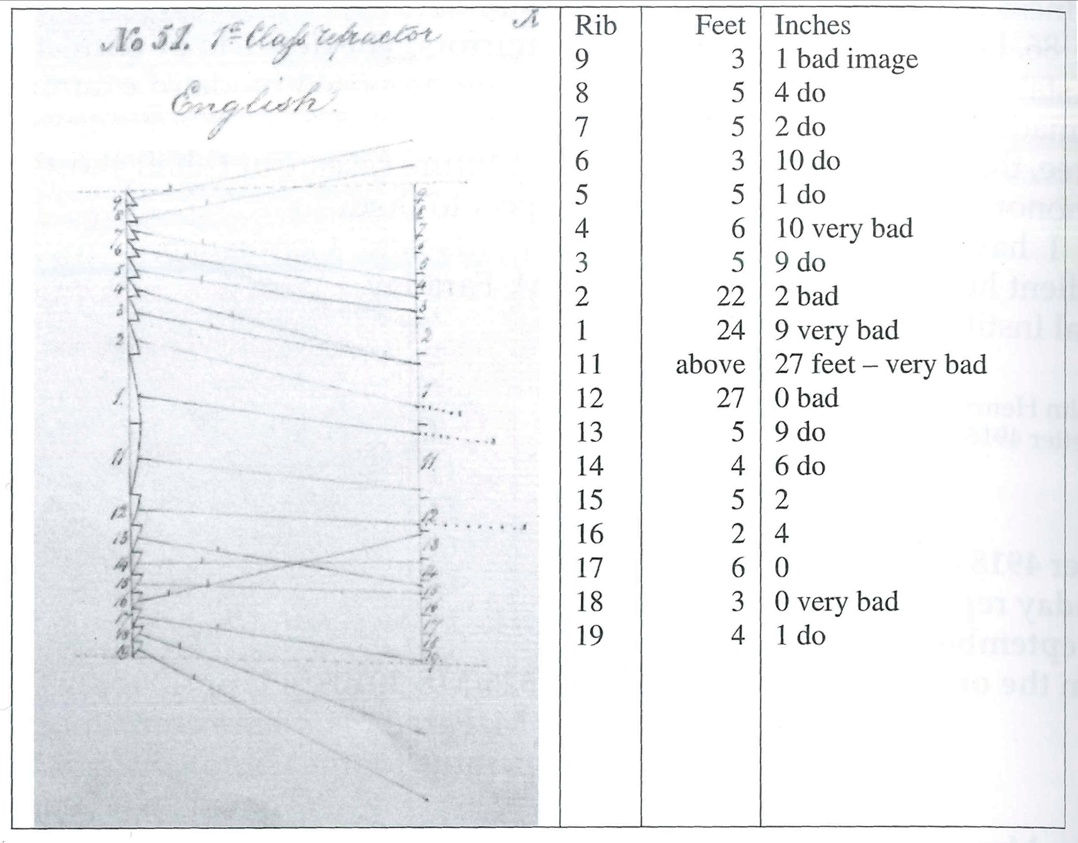
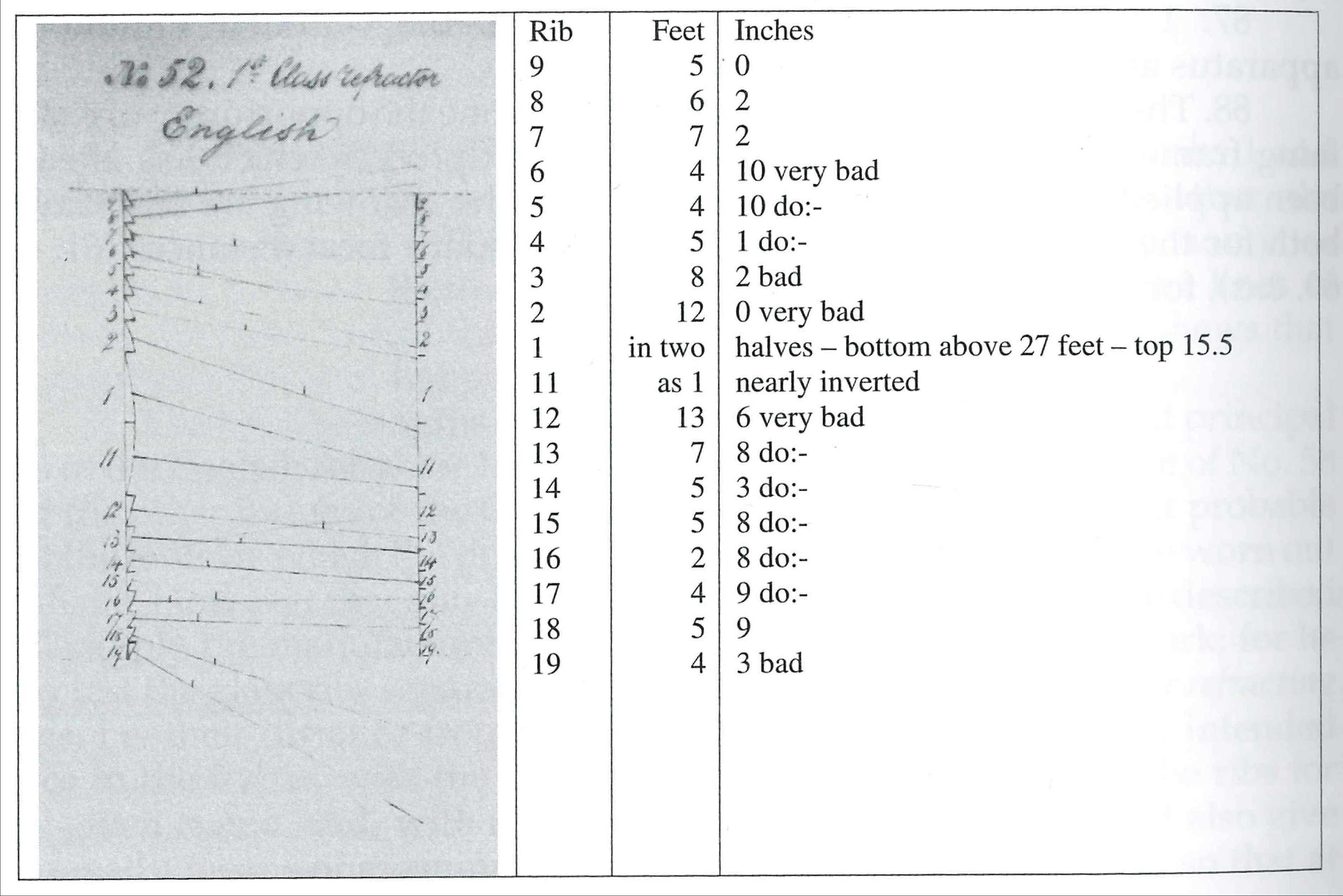
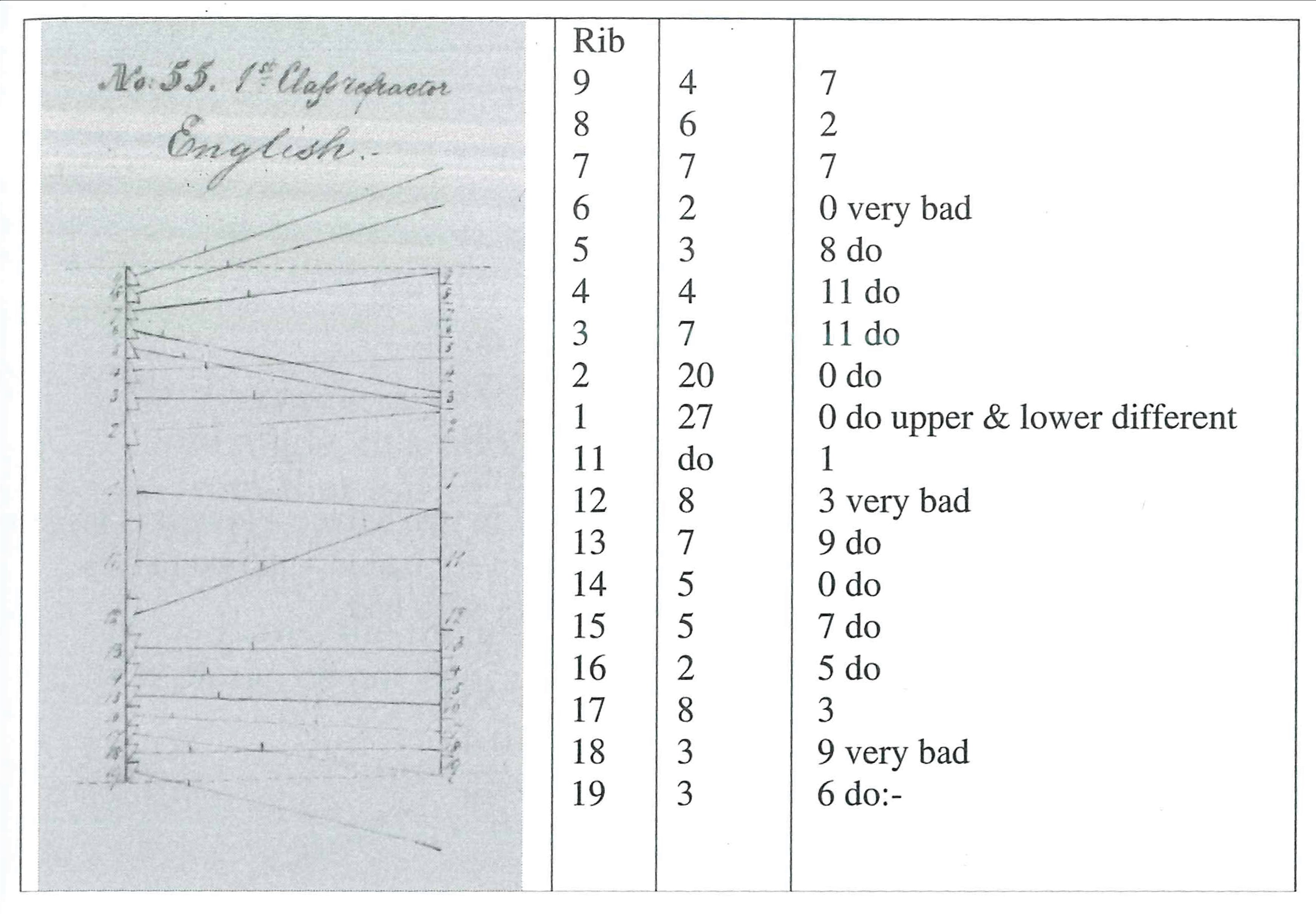
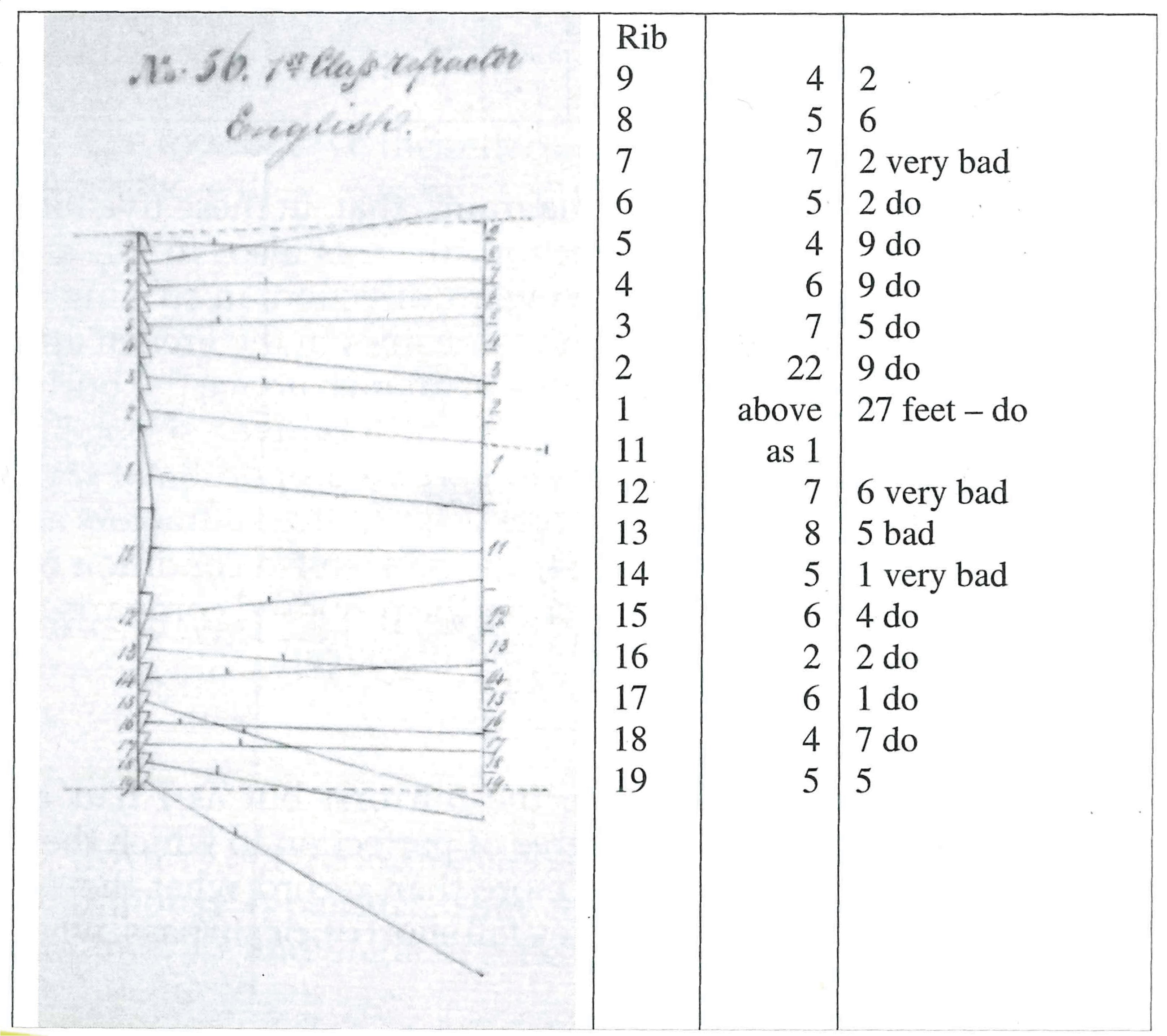
88. The dismounting of the refractors gave one the opportunity of examining frames No. 51. 52. 55. 56. and 57., by that process which has already been applied to Nos. 53. 54. and 58. <(38)>; and the following are the results, both for the medium ray (48. 49.) and the secondary focal distances (61. 63. 69. &c:), for these frames.
89.
90.
91.
92.
93.
94. It will readily be seen by the diagrams, that, in these five refractors, besides the great irregularities of direction, there is also, in all, a general tendency of the medium rays to a downward direction, in striking contrast with the general upward direction of the same lines in the French apparatus (55.) for the same assumed focus of ⅝ths of an inch above the burner. This would have the effect of making the English refractors give a strong light near at hand, but would rob the distant place of it’s due proportion of rays.
95. In the matter of the secondary foci (63. 69) these refractors are as far from the French refractors as Nos. 53, 54, and 58 were:- a condition of things which makes me more anxious than ever for the proposed comparison of the English and French refractors at Purfleet and Blackwall.
<-><-><->
96. I then proceeded to examine the mirrors; but as I had no standard of the reasonable, or possible, degree of perfection to which they might be worked and arranged, I can do no more than record what they actually performed; without judging whether they fall short of, or surpass, what might properly be required.
96½. Theoretically, a mirror M is intended to
reflect the diverging rays which fall on it from a certain point F, at a given distance and angle, in a horizontal parallel beam; the required divergence of the beam from that mirror for light house purposes, being obtained by the great size of the flame which is usually placed at F. (62.). To obtain this end the mirror must have a certain degree of concavity, dependant upon the distance of the focus F and the inclination of the incident rays with the mirror. If the mirror be plane, or not concave enough, the reflected rays will diverge more or less.
If it be too concave the reflected rays will come to a second focus S and there crossing, will
afterwards diverge like those rays which, with so many of the ribs of the English refractors (70, 73, 74, &c.) are sent to a second focus and then diverge for ever.
<-><-><->
97. To carry out the examination the mirrors were numbered as arranged in the lighthouse apparatus. They form eleven tiers of 22 mirrors each; the focal distance, -”- and angle of reflection varying for each of these tiers, but remaining the same for the mirrors of any one tier. These angles and distances were noted, and then an apparatus was made by which the mirrors could be examined with facility one by one; for any mirror of a tier being laid on a certain shelf, was at the same angle with, and distance from, a given object (21. 39.) as it was in the lighthouse apparatus from the focal point. It was then easy at any given distance (and I chose 20 feet for that purpose) to ascertain the width of the reflected beam by observing the places where the object appeared and disappeared in the top and bottom of the mirror; and as the reflected beam ought by theory to be only of the width of the projection of the mirror, it was easy to deduce whether the mirror caused the reflected rays to travel rightly or not. Thus the object at F,
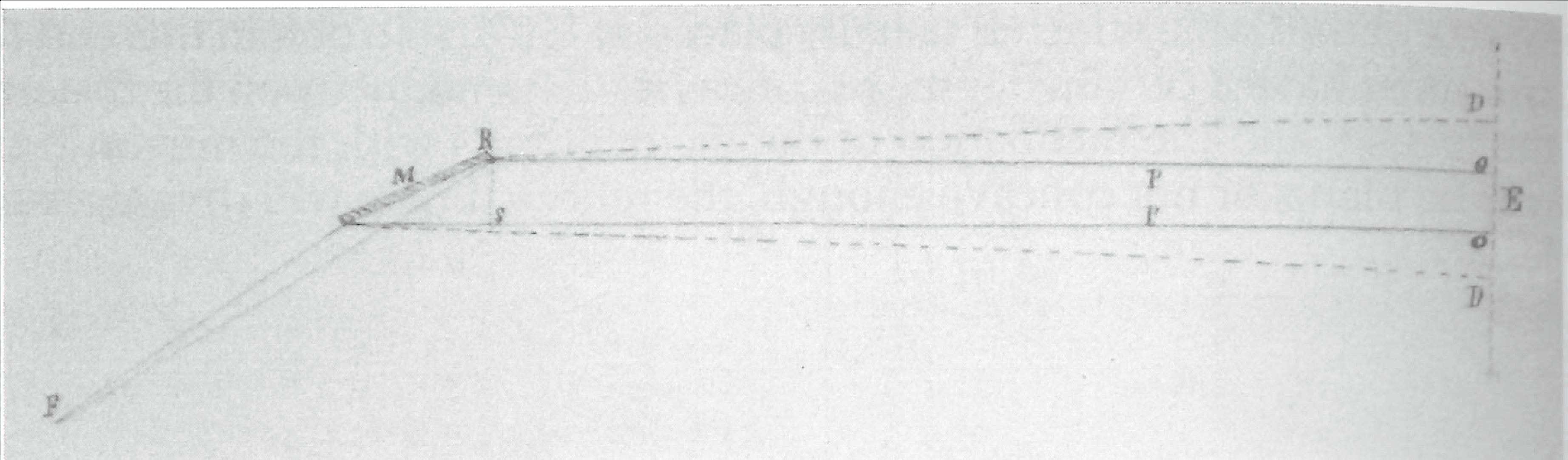
or the focal point, may be considered as sending rays to the mirror M., which being reflected, pass it is supposed, in parallel directions P.P. to the distance of 20 feet O.O. or to any greater distance. Whether the rays are parallel or not may be ascertained sufficiently near for all practical purposes thus: let the eye be placed at E, and observe the projection of the mirror M. i.e. the portion of a rule intercepted between R and S, or the apparent upper and lower edges of the mirror the rule being vertical to the line of sight. If this distance be 4 inches, record it; then move the eye up and down at O.O. and observe where the image F appears and disappears in the mirror M. If the points of appearance and disappearance be at O.O. and the distance between them be 4 inches, then the reflected rays are parallel, as required; but if they be at D.D and these points be 12 inches apart, it is clear that the rays still diverge, and that, consequently, a loss of light, which increases very rapidly for great distances will be the result, exactly in the same manner as with the diverging refracted ray after it has passed it’s second focus. (63.).
98. The mirrors are by no means regular in their form, nor do the two surfaces of the glass agree. There are some cases in which the first surface gives a beam in the contrary direction to the second; and so the image from the one surface enters direct, and from the other, reverse <(42)>. In the observations, I always used the image reflected from the metallic surface, or the silvering of the glass. The numbers though expressed to half and quarter inches are only approximations, for the irregularity of form prevented accurate results; nor is such nicity [sic] required in this practical kind of examination.-
99.

100. It will be seen, that, in the tables, there is given, for each tier of mirrors, the distance of the focal point or place of the lamp in the frame, and, also, the projection or apparent width of the mirror, as seen from a distance, in the horizontal line. Then comes the width which the beam ought theoretically, to have; next the width which it really has from any given mirror; and finally the width it would have if the mirror were quite flat or plane; all at the distance of 20 feet. Thus the mirrors of tier I should give a beam 7½ inches deep; but mirror 10 gives a beam 11 inches deep, and mirror 17, one 20¾ inches deep; whilst a plane mirror would have given one 37¾ inches deep. So, as the object of the mirrors of tier I is to contract a beam 37¾ inches deep to a depth of 7½ inches, it will be seen that mirror 10 does far more towards attaining that object than mirror 17.
101. The tables shew, that except for Nos. 5 and 6 of tier IV.- 12 of tier V.- 16 of tier VII.- and 3 of tier VIII, being five cases in 242 the mirrors do not produce an effect equal to, or more than, that required. Generally they fall very far short of that which they ought to perform. Like the refracting ribs of the dioptric part of the apparatus they have a diverging beam, but they are -”- the contrary of the ribs in this, that they have no secondary foci; they do not bring the issuing rays sufficiently together.
102. It is quickly seen that the mirrors of the same tier are very unlike in their action. I do not know how far this is inevitable <(96)>; nor whether the mirrors are ground to their present shape, or only softened by heat and allowed to take their form on a mould, as is practised for the production of concave and convex silvered mirrors. I should have expected that either process would have given more uniform results than those really obtained with these mirrors. But I have no standard of practical workmanship to refer to.
103. The mirrors 12 of tier V, and 16 of tier VII, are too concave and give and inverted image at the distance of 20 feet. Their secondary foci are, for the first 8 feet 3 inches and for the second 8 feet 7 inches.-
104. It would be very easy and perhaps in some respects, better, to express the power of the mirrors by the angle formed between the two rays, which, emanating from the focus, are reflected at the upper and lower edges of the mirrors. Thus, with tier I. these rays reflected from an accurately adjusted mirror, and so rendered parallel, would

But I have thought the former mode of statement the best for the present:- if the angles are required, they are easily deduced from the consideration that the two lines are 20 feet in length, and separate at one end by a space equal to the projection of the mirror and at the other by the interval recorded in the table opposite any particular mirror.-
105. A still better practical mode of registering the results both for the reflectors and the refractors; i.e. provided the mode of examination and its conclusions are admitted to be correct, may be adopted hereafter, by using the chord, or what is the same thing, practically, for these small arcs, the sine of the angle, to express the divergence;- for the number used will then shew at once, the width of the beam at any given distance from the lighthouse; for instance, a correctly adjusted mirror in tier I would have this

These numbers would shew that at the distance of a mile, these fractions of a mile would express the width of the beam nearly; or that at the distance of 1000 yards, the beam from the correct mirror would still be only the 7.5 inches, whilst that from mirror 10 would be 14.6 yards increased by 7.5 inches, that from mirror 17, above 55 yards, and that from a plane mirror above 126 yards. These numerical expressions are very easily obtained.
106. With respect to the medium ray <(48)> of any particular mirror, I have taken no note of that at present;- for, according to the mode of adjustment adopted by Mr. Wilkins when fixing the mirrors, that line ought to be horizontal. Whether it is ultimately so or not can only be determined by the final examination which the apparatus should receive, before it is sent to it’s destination.
107. The mirrors for tiers VII. VIII. IX. X. and XI. i.e. the bottom tier above the refractors and all the tiers below, are of the same width and size; and, though intended for places at very different distances from the lamp or focal point, yet no mark is put upon them, nor any distinction made. In fact any one of them is put into any place in those five tiers where it may conveniently fit in;- no restriction is made, or direction given, relative to any supposed necessity of applying certain mirrors in a certain tier. Now it is true, that though the mirrors are at different distances from the focal point, the effect of the angle at which they are placed tends to compensate that difference. A mirror which is right in its concavity and angle for a long focal distance may be placed at such an angle as to be practically right in it’s concavity for a shorter distance; and in the Lighthouse apparatus, where the focal lengths and the angles of incidence are necessarily fixed for each tier, the differences from tier to tier are such as tend to compensate each other.
108. But as I was bound to look at practical results only, I thought it desirable to examine these mirrors for the two extreme cases between which they might be placed, to see, in fact, if they might be sorted and arranged so as to give any better result than that already registered;- the following is the result.
109. The table gives the required width of beam in position a being the position of the mirrors in that tier which is nearest to the refractors; and also in position b or that of the mirrors in the tier furthest from the refractor;- it gives also the actual width of beam from every one of the mirrors of the five rows in either of these positions and it gives the width of a beam from a plane mirror of the same size in either of these places.
110.

111. From this table it will be seen how few in number are the mirrors which approximate to the effect desired; i.e. how few could be picked out, which in any situation, upon these five tiers, would produce a ray not more than double the width of the required ray at the distance of 20 feet. There are but sixteen such mirrors out of the whole number of 110.
112. Allow me again to state that the numbers I have given do not pretend to perfect accuracy; for I have neglected small quantities as not to be expected or required in a matter which is to be practical, and in which an approach to perfection is the utmost that can be hoped for2.
I have the honor to be | My Lords and Gentlemen, | Your very obedient humble Servant | (signed) M. Faraday
Royal Institution | Septr. 16th. 1840.
Please cite as “Faraday1312a,” in Ɛpsilon: The Michael Faraday Collection accessed on 27 April 2024, https://epsilon.ac.uk/view/faraday/letters/Faraday1312a