To Thomas Andrews 18th Sept. 18521
Queenwood College near Stockbridge | Hants– 18th Sept. 1852
Dear Sir.
I think I heard you express a wish to see a good and convenient electro-magnet previous to getting one made for yourself. If the following sketch of the instrument I use, and which I find to be very serviceable, be of any service to you it will give me much pleasure.

Instead of the common horseshoe form the magnet is composed of two upright soft iron pillars united at the bottom by a cross piece of the same material. The contact of the ends of the cylinders with the cross piece must be very good – otherwise a loss of power will ensue. The cross piece is fastened to the cylinders by a pair of strong screws which pass through the former and pierce the interior of each cylinder – the latter being fitted with a thread for the purpose
Height of the cylinders 8 7/8 inches
diameter —————— 1 5/8 inches
Distance from centre to centre 4 ¼ inches
Breadth of cross piece 2 inches
Depth —————— 1 ¼ —
Length —————— 8 inches
The whole rests upon a slab of mahogany 12 ½ inches by 10 ½, being made fast to the wood by screws passing through the crosspiece
Round each cylinder is a coil of copper wire. The coil is made exactly on the principle of the common spool (I’m not sure whether this is the term ladies give the article round which thread is wound) the coil slips down along its cylinder being quite close to it – the aperture through its centre being not much more than sufficient to permit the cylinder to pass through.
Height of coil 5 7/8 inches
diameter 3 7/8 —
Each coil contains 6 lbs of copper wire – [overspread] with cotton – silk is expensive, and when the cotton is soaked in a solution of shell lack2 it is equally good as an isolator.
In each coil I have caused two wires to be wound – you can either send the current through both at the same time as through as single unit of twice the thickness, or you can send it through the whole length of the single wire –
By reference to the dimensions you will see that the cylinders are higher than the coils – The latter I cause to embrace the centre of the cylinders by causing them to rest upon a ring of wood which raises them to the required height – A similar ring of wood is placed above each coil high enough to bring it to the same level as the upper end of the cylinders.
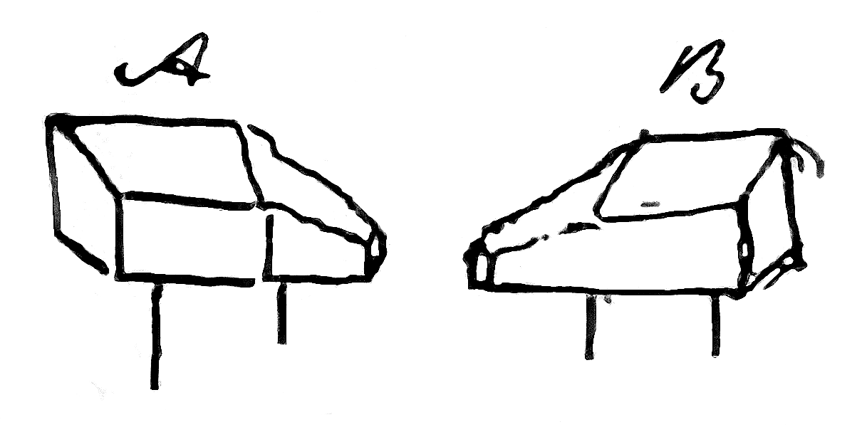
on the ends of the cylinders two moveable pieces of soft iron are placed which you can place with their flat faces opposite and as close as you please or with their points opposite as in the figure – between these masses the crystal or other body experimented with is hung –
Over my instrument is a glass case of this shape having a tube of glass fixed on the top and through which a silk fibre descends – the substance to be examined is attached to the fibre.

I hope you will understand me –
very sincerely yours | J Tyndall
Enclosed is a specimen of the wire used in the coils.
Science Museum, Wroughton MS 350/1/128
Please cite as “Tyndall0660,” in Ɛpsilon: The John Tyndall Collection accessed on 30 April 2024, https://epsilon.ac.uk/view/tyndall/letters/Tyndall0660